
The Gig Man’s Life | 3D Printing, OpenSCAD, and the Art of Figuring Things Out
Sometimes a project starts with a simple question: Can I make this work?
And then, before you know it, you’re several revisions into a design, writing new OpenSCAD modules, adjusting tolerances, experimenting with structural supports, and realizing that what started as a box has become an entire construction system.
Well, that’s pretty much what happened with my latest 3D-printing project.
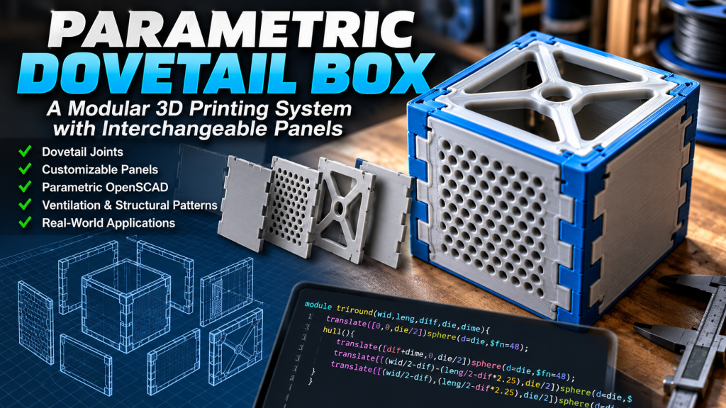
I’ve now posted my Parametric Dovetail Box project on Thingiverse, where others can take a look at the design and experiment with it themselves.
View the Parametric Dovetail Box on Thingiverse
It Started With a Dovetail
One of the things I’ve been experimenting with in 3D printing is creating reliable mechanical connections without depending on screws, glue, or other hardware to hold everything together.
Dovetail joints have been used in woodworking for centuries. The principle is fairly straightforward: two pieces interlock through their geometry, creating a connection that resists being pulled apart in certain directions.
But translating that idea into 3D printing introduces some interesting challenges.
You have to account for printer tolerances, material shrinkage, layer orientation, and the fact that a connection that looks perfect in CAD might be nearly impossible to assemble after printing.
So I started developing a parametric dovetail system in OpenSCAD.
Rather than manually drawing every tooth, I created modules that calculate the number of joints based on the dimensions of the box.
Change the box width, length, or height, and the dovetail pattern recalculates.
That was the first major step.
The Difference Between Designing a Box and Designing a Construction System
Here’s where my thinking started going in another direction.
I didn’t want to design one box, print it, and then start over the next time I needed something different.
I wanted a system where the physical construction remained consistent even when the box dimensions or panel designs changed.
That’s why I separated the model into individual components.
The panels are generated independently, but their dovetail geometry follows the same construction rules.
This means I can print a solid panel today, design a ventilated panel tomorrow, and potentially use either one within the same enclosure, provided the dimensions and joint configuration match.
And because the entire project is written in OpenSCAD, I don’t have to redraw everything to make those changes.
I adjust the variables, regenerate the model, and test the result.
That’s the advantage of parametric design.
Making the Panels Do More Than Just Close the Box
Once the dovetail connections were behaving the way I wanted, another question came up.
Why should every panel be solid?
There are plenty of situations where a box needs ventilation, a recessed surface, or a structural pattern that reduces material while maintaining useful rigidity.
So I started adding cutting options.
The current design allows several different panel treatments, selected through a variable in the OpenSCAD source.
One option produces a recessed panel with perforations. Another produces the recess without the holes. A third generates perforations through the full panel thickness.
And then there’s the latest experiment: the X-braced panel.
Four Triangles, a Circle, and Some Interesting Geometry
This particular cutting pattern started with four triangular shapes.
But instead of constructing the triangles from ordinary flat polygons, I used spheres and OpenSCAD’s hull() operation.
For each triangular cutting shape, three spheres establish the points of the geometry. OpenSCAD then generates a rounded solid connecting those spheres.
Repeat that process four times around the panel center, and you get four rounded triangular cutting volumes.
When those volumes are subtracted from a solid panel, the material left behind forms an X-shaped structural support.
I also added a sphere at the center, producing a circular opening between the diagonal supports.
The interesting part is that the position of every sphere is calculated using the panel dimensions and adjustable offsets.
That means the same module can be reused on different-sized panels.
And because the geometry is three-dimensional, changing the depth and position of those cutting volumes also opens up possibilities for rounded openings and different surface profiles.
It’s a small example of how something that looks complicated can be constructed from a handful of simple geometric operations.
Structural Infill Instead of Just Slicer Infill
This is another area where I’ve been thinking about 3D printing a little differently.
Normally, when we talk about infill, we’re discussing the pattern a slicer generates inside a printed object.
But what if some of that structural thinking happens in the CAD model itself?
The X-braced panel is an example.
Instead of printing an entirely solid wall and relying on internal slicer infill, the design deliberately leaves structural material running diagonally between the corners and the center.
In principle, that can provide useful load paths while reducing the amount of material in the panel.
Of course, the actual strength depends on the dimensions, print orientation, material, and forces applied. A geometric brace isn’t automatically stronger just because it looks like one.
That’s why physical testing matters.
And that’s also one of the things I enjoy about 3D printing. You can work out an idea mathematically, print it, handle it, and find out where the theory meets reality.
The Press-Fit Experiment
One of the more satisfying parts of this project has been working with the actual printed components.
The dovetail joints are designed around a press fit.
That means assembly requires some pressure, but the connection is intended to remain secure without additional fasteners.
I’ve already been experimenting with printed panels that require a deliberate push to seat the joints, and the resulting assemblies have shown encouraging resistance to racking.
That doesn’t mean every printer will produce exactly the same fit.
A tolerance that works on my printer may need adjustment on another machine, particularly when changing filament types or printing conditions.
That’s another reason to make those values adjustable rather than burying them in the geometry.
The goal isn’t to claim that one tolerance is universally perfect.
It’s to make the system adaptable.
Why I Added Comments to the OpenSCAD Code
There’s another detail worth mentioning.
I went through the source code and added comments explaining what the various parameters control.
That might sound like a small thing, but it matters when a project starts growing.
When you’ve got variables controlling wall thickness, dovetail dimensions, joint spacing, cutting geometry, sphere diameters, offsets, and panel selection, it’s easy to forget why a particular calculation exists.
Especially when you come back to the project several days or weeks later.
Having those explanations in the source makes the design easier to understand and experiment with.
And if someone else downloads the project and wants to modify it, they’re not left trying to reverse-engineer every variable before making a change.
What Could You Use This For?
I’ve already been considering several applications.
A ventilated enclosure could be useful for electronics or small sensors.
A perforated container could potentially serve as a reusable desiccant holder, allowing air to circulate through the drying material.
Different panel treatments could be useful for small organizers, custom equipment enclosures, or other projects where you want to keep the same basic construction method.
And because the dimensions can be changed, the design isn’t limited to one particular size.
Naturally, each application introduces its own requirements. A desiccant container needs openings small enough to retain its contents, and an electronics enclosure may need additional mounting features or thermal considerations.
But the underlying construction system provides a starting point.
Why Put It on Thingiverse?
Because this is the kind of project that benefits from experimentation.
I’m not presenting this as the final word in dovetail construction or modular enclosures.
It’s an evolving design.
There are things I want to test, refinements I want to make, and other cutting patterns I may add.
But at some point, a project becomes useful enough that it makes sense to share it rather than keeping it entirely on my own computer.
Someone else might take the concept in a direction I haven’t considered.
They might modify the panel geometry, discover a better tolerance for a particular material, or use the construction system for something completely different.
That’s part of the appeal of sharing parametric designs.
The Gig Life Is More Than Driving
This is also something I keep coming back to when talking about The Gig Man’s Life.
Yes, rideshare and gig work are major parts of what I discuss.
But the gig life, at least the way I look at it, is also about what you do with your time, your interests, and the opportunities to learn something new.
Sometimes that means working with Raspberry Pis, experimenting with electronics, writing code, designing mechanical parts, or sitting in front of OpenSCAD wondering whether a particular arrangement of spheres and hull operations will produce the result you have in your head.
And sometimes it means printing a bunch of plastic pieces just to find out whether your calculations were right.
That’s not wasted effort.
That’s learning through construction.
The box itself is useful. But the ability to develop a reusable system, understand why it works, and improve it over time is arguably more valuable.
Download the Design
The Parametric Dovetail Box project is available on Thingiverse.
Parametric Dovetail Box – View the Project on Thingiverse
If you’re interested in OpenSCAD, 3D printing, modular construction, or experimenting with mechanical connections, take a look.
And if you modify the design or come up with an interesting use for it, I’d be interested in seeing what you build.
Because sometimes a box isn’t just a box.
Sometimes it’s the beginning of another project.
The Gig Man’s Life — where rideshare, technology, creativity, and a questionable number of new projects all manage to coexist.