
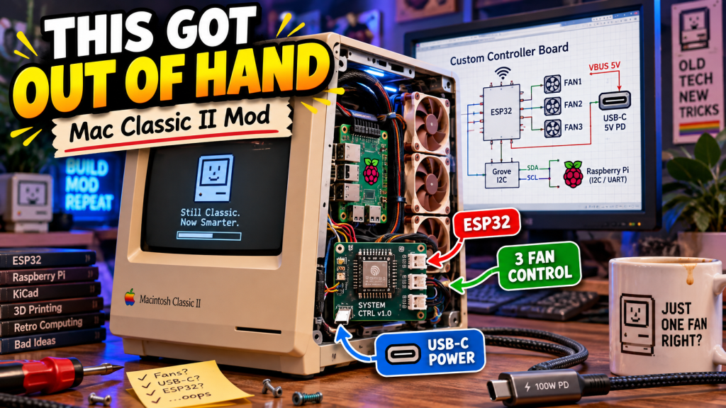
What started as a fairly straightforward idea — modernize a Macintosh Classic II case with a Raspberry Pi and make the cooling work properly — has now moved well beyond “put a computer in an old case.”
The project is becoming a complete little system.
There is the Raspberry Pi itself, the display, the 3D-printed internal structure, the cooling layout, the power distribution, the custom controller board, the soft-power logic, the temperature monitoring, the USB-C power plan, and now even the possibility of audio and additional environmental sensors.
And the more I work on it, the more the design starts to make sense as one integrated machine instead of a collection of parts.
The Controller Board Has Become the Center of It
The biggest change has been the custom ESP32-S3 controller board.
Originally, the main reason for adding a controller was fan management. The Macintosh Classic II case has very little room, and I wanted to maintain the vertical airflow design that has already performed well in testing.
That led to three independent 4-pin fan channels.
Each fan gets:
- 5-volt power
- ground
- PWM speed control
- tachometer feedback
The ESP32 can therefore control the speed of each fan independently and also verify that each fan is actually spinning.
That alone would have made a useful controller.
Naturally, I did not stop there.
Temperature Monitoring
The board now includes temperature monitoring so the fans do not simply run at fixed speeds.
There is already provision for a local temperature sensor, plus two additional Grove-style sensor connectors.
That gives me room to monitor different parts of the enclosure.
One sensor could sit toward the top of the case where warm air collects.
Another could sit near the buck converter.
The second Grove port could eventually be used for something else entirely, such as humidity monitoring or another environmental sensor.
That is one reason I like using standardized sensor connectors instead of hard-wiring every future possibility into the PCB.
The board can evolve without having to be redesigned every time I decide I want another measurement.
The ESP32 Is Also Becoming the Power Manager
The controller is no longer just watching temperatures.
It is also going to manage the Raspberry Pi’s power.
The plan is for the ESP32 to remain powered whenever the machine is plugged in. A soft-power button on the rear of the Macintosh will signal the ESP32 that I want the system to start.
The ESP32 then enables a high-current P-channel MOSFET and sends regulated 5-volt power to the Raspberry Pi.
That means the sequence can eventually look something like this:
Press button → fans start → Pi receives power → Pi boots → Pi reports that it is alive.
Shutdown can work in reverse.
Instead of simply cutting power to Linux, the ESP32 can send a shutdown request to the Pi, wait for the Pi to confirm that it has shut down, and then remove its 5-volt supply.
That makes the controller much closer to a little supervisory computer.
The Pi and ESP32 Will Talk to Each Other
I added a five-pin control connector between the ESP32 and Raspberry Pi.
The current plan gives me:
- UART transmit
- UART receive
- Pi-alive signal
- shutdown-request signal
- common ground
The ESP32-S3 can route one of its hardware UARTs onto the GPIO pins I chose, so this does not need to be an old-fashioned bit-banged software serial connection.
The serial link opens up a lot of possibilities.
The Pi can send its CPU temperature to the ESP32.
It can report system status.
The ESP32 can report fan speeds, case temperature, power state, and sensor information back to the Pi.
That means the Raspberry Pi can eventually host a full control panel showing what the little management board is doing.
And yes, I am still considering making that interface look like an old Macintosh control panel.
Because if I am going to over-engineer a fan controller, I might as well make it look correct.
USB-C Is Taking Over the Power System
One of the more interesting changes came from looking at how the machine itself should receive power.
The original plan involved reusing a 19-volt laptop-style power supply.
That would work.
But USB-C Power Delivery makes the project much cleaner.
I found small USB-C PD trigger boards that can negotiate fixed voltages such as:
- 5 V
- 9 V
- 12 V
- 15 V
- 20 V
That means the rear power connector on the Macintosh could potentially become USB-C.
The external power architecture would then be:
USB-C charger → PD trigger board → buck converter → 5-volt internal distribution.
The trigger board could request 20 volts, or possibly 15 or 12 volts depending on what ultimately makes the most sense for the buck converter and total load.
Using a higher input voltage also keeps the current lower before the buck converter, which makes the wiring and connector requirements easier to deal with.
So instead of having a proprietary or laptop-style barrel connector on the rear of the Macintosh, the whole machine could simply use a decent USB-C laptop or GaN charger.
That is a pretty attractive upgrade.
USB-C to the Raspberry Pi Too
The Pi power connection is also moving toward a modular USB-C design.
Rather than soldering a USB-C receptacle directly to the custom board, I have been looking at panel-mount and breakout-style USB-C connectors that expose the pins I need.
That gives me a replaceable mechanical component.
If somebody damages the USB-C connector later, I do not have to repair the main controller PCB.
I simply replace the socket.
The better six-pin style connectors expose:
- VBUS
- ground
- D+
- D-
- CC1
- CC2
That means the controller board can still provide the proper CC resistors and behave as a correct USB-C source while the connector itself remains replaceable.
The Pi then gets its controlled 5-volt supply through a short internal USB-C cable.
There may end up being a ridiculous number of USB-C cables inside this old Macintosh.
I am okay with that.
Main Power Distribution
The custom board will receive the regulated 5 volts from the buck converter through a screw-terminal connection.
From there, the board becomes the main 5-volt distribution point.
The 5-volt rail feeds:
- the ESP32
- the three fans
- the display
- the sensor system
- the Pi power switch
- eventually any other low-voltage accessories
The Raspberry Pi branch is switched.
The fans and ESP32 remain available to the controller independently.
Once the board moves fully into PCB layout, the plan is to use a two-layer board.
The bottom layer will be largely a ground plane.
The top will carry the main 5-volt distribution path and the various signal traces.
The Pi and fan power sections will use substantial copper rather than little signal-width traces.
This is one of the reasons the project has become a real PCB design exercise instead of simply wiring modules together.
Through-Hole Where Possible, Surface-Mount Where Useful
I am still leaning toward making most of the board easy to hand-solder.
The fan-control transistors are 2N3904s in through-hole packages.
The resistors can be conventional axial through-hole parts.
The screw terminals, headers, and sensor connectors can all be through-hole.
The main Raspberry Pi power MOSFET, however, is likely to remain surface-mount.
That may actually be a good introduction to doing some SMD soldering without turning the entire board into a microscope project.
The USB-C connectors will probably remain on separate breakout or panel-mount assemblies, which avoids having to hand-solder the tiny receptacle pins directly onto the main PCB.
Then There Is Audio
Because apparently this project needed another direction.
I started thinking about scavenging small powered PC speakers.
An old set of desktop speakers could provide:
- speakers
- amplifier board
- volume control
- possibly a headphone jack
- miscellaneous useful hardware
A 3D printer makes that kind of scavenging far more practical because the original enclosure no longer matters.
If the amplifier is useful, I can simply design a new mount for it.
Then another thought occurred to me.
The ESP32-S3 itself can produce digital audio.
With a small I²S amplifier board, the controller could potentially play:
- startup sounds
- shutdown sounds
- warning tones
- error alerts
- status sounds
And it could do that even if the Raspberry Pi is not running.
The controller board could therefore eventually become the machine’s power manager, fan controller, environmental monitor, communications controller, and sound controller.
All because I originally wanted to manage airflow.
The Mechanical Side Is Still Evolving
The internal mechanical design remains one of the more enjoyable parts.
The Raspberry Pi is vertically mounted in the airflow path.
The fan arrangement is built around moving cool air upward through the case.
The printed structures use dovetails and modular mounts rather than relying on one giant printed object.
That gives me the ability to remove and change individual parts without rebuilding the entire interior.
The measured thermal performance so far has been encouraging.
The basic vertical airflow design has kept the Raspberry Pi far below its thermal-throttling range, even under artificial load.
So the foundation of the cooling concept seems sound.
Now the electronics are catching up with the mechanical design.
Purchases Are Starting to Reflect the Final Architecture
The parts I am now looking at are no longer random experiments.
They are increasingly tied to the architecture.
The current shopping list includes things such as:
- USB-C PD trigger boards
- panel-mount USB-C connectors
- USB-C cables
- motherboard-style 4-pin fan headers
- Grove/JST sensor connectors
- screw terminals
- through-hole transistors and resistors
- the high-current P-channel MOSFET
- possibly small I²S amplifier hardware
- possibly salvaged or replacement speakers
The interesting part is that each purchase now has a defined place in the system.
That is usually the point where one of my ridiculous projects starts becoming real.
The Video Was Basically the Project Meeting
I also did a debrief video showing where the design currently stands.
That ended up being a fairly accurate demonstration of how the project is developing.
There is no polished engineering department behind this.
It is me looking at the design, moving things around, realizing another feature would be useful, asking whether something is electrically reasonable, and then adding it to the project.
Sometimes the answer is:
“Yes, that will work.”
Sometimes it is:
“No, you have that transistor backward.”
And sometimes it is:
“Technically yes, but now you’ve turned your fan controller into a system-management computer.”
Those are usually the more entertaining moments.
AI Is Accelerating the Process, Not Inventing the Project
This project has also become one of the clearest examples I have had of what AI assistance actually looks like when it is used as part of making something.
AI did not decide to put a Raspberry Pi inside a Macintosh Classic II.
It did not decide that the Pi should be vertical.
It did not decide to build a custom cooling cage.
It did not decide that the fan controller should become a power-management system.
It certainly did not decide that the control interface should eventually look like an old Mac.
Those are my bad decisions.
What AI has done is dramatically shorten the time between:
“I wonder if this will work?”
and:
“Okay, here’s how I can test it.”
That has been especially noticeable while learning KiCad.
Instead of spending hours searching through tutorials to figure out where a command is or what symbol I need, I can ask the question while I am working and continue immediately.
I still have to place the parts.
I still have to draw the schematic.
I still have to choose the components.
I still have to decide what the machine should actually do.
But the process is moving much faster because I am spending more time building and less time searching for the next piece of information.
Where the Project Stands Now
The project currently has a fairly clear direction.
The Macintosh Classic II will contain a Raspberry Pi-based computer with a vertically oriented cooling system, a custom ESP32-S3 management board, USB-C-based power, multiple temperature sensors, independent fan control, soft-power management, serial communication between the Pi and controller, and a modular internal wiring system.
There are still plenty of things to finalize.
The PCB needs to be physically laid out.
The exact connectors and footprints need to be locked down.
The USB-C PD input voltage needs to be chosen.
The power system needs to be tested under full load.
The firmware needs to be written.
The control interface still needs to be designed.
And apparently I may now be adding speakers.
But this is no longer a vague idea.
The pieces are beginning to form an actual system.
And that is usually where the project gets dangerous.
Because once I can see how all the pieces fit together, the next question is rarely:
“Should I keep going?”
It is usually:
“What else can I make this thing do?”